
UXO route survey for ROVCO at Pentland Firth
Overview
OEG's subsea division was commissioned by ROVCO to provide a suite of geophysical UXO route survey services for an interconnector cable route between the Island of Hoy in the Orkney Islands and Murkle Bay on the Scottish Mainland.
Client
ROVCO
Location
Pentland Firth, Scotland


Challenges
Working in the very nearshore area with towed sensors to achieve full coverage seabed data to provide a seamless data set from sea to land. This was overcome by diligent survey planning around tidal conditions and through the local knowledge and skill of the vessel master, which allowed not only the capture of data but also a safe and efficient operation with no danger to personnel, vessel or equipment.
Workscope
Geophysical, topographical and UXO survey work between the transition joint bays at either end of the cable route, sectioned into nearshore and onshore survey works and detailed as follows:
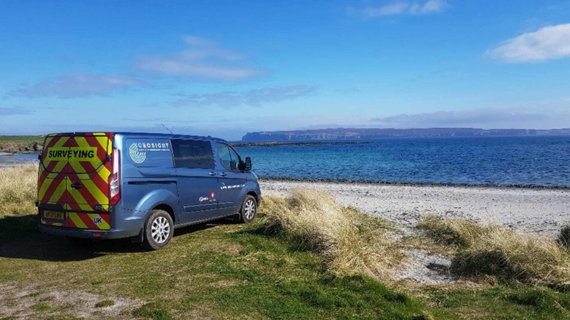
- Land Survey - From the onshore transition joint bay (TJB) to MLWS, ensuring a 50m overlap with the nearshore survey. The land survey will extend 200m inland from TJB.
- Nearshore Survey - From the overlap with the land survey, and seaward of the MLWS, to the 10m LAT contour, ensuring a 250m overlap with the offshore survey. Survey corridor is 70m wide based on the center of the RPL.
Solution
OEG's subsea division deployed their owned and operated modern geophysical survey equipment suite to achieve the project objectives. Geophysical survey equipment deployed on the project included:
- MBES - Norbit iWBMS high-resolution multibeam echosounder (MBES) with integrated Applanix POS MV position and attitude reference system.
- SSS - Edgetech 4125 Sidescan Sonar utilizing Edgetech’s full spectrum CHIRP technology.
- Sub Bottom Profiler (SBP) - Innomar SES-2000 parametric sub bottom profiler capable of acquiring full-waveform 24 bit data that can be processed with any seismic software (SEG-Y format).
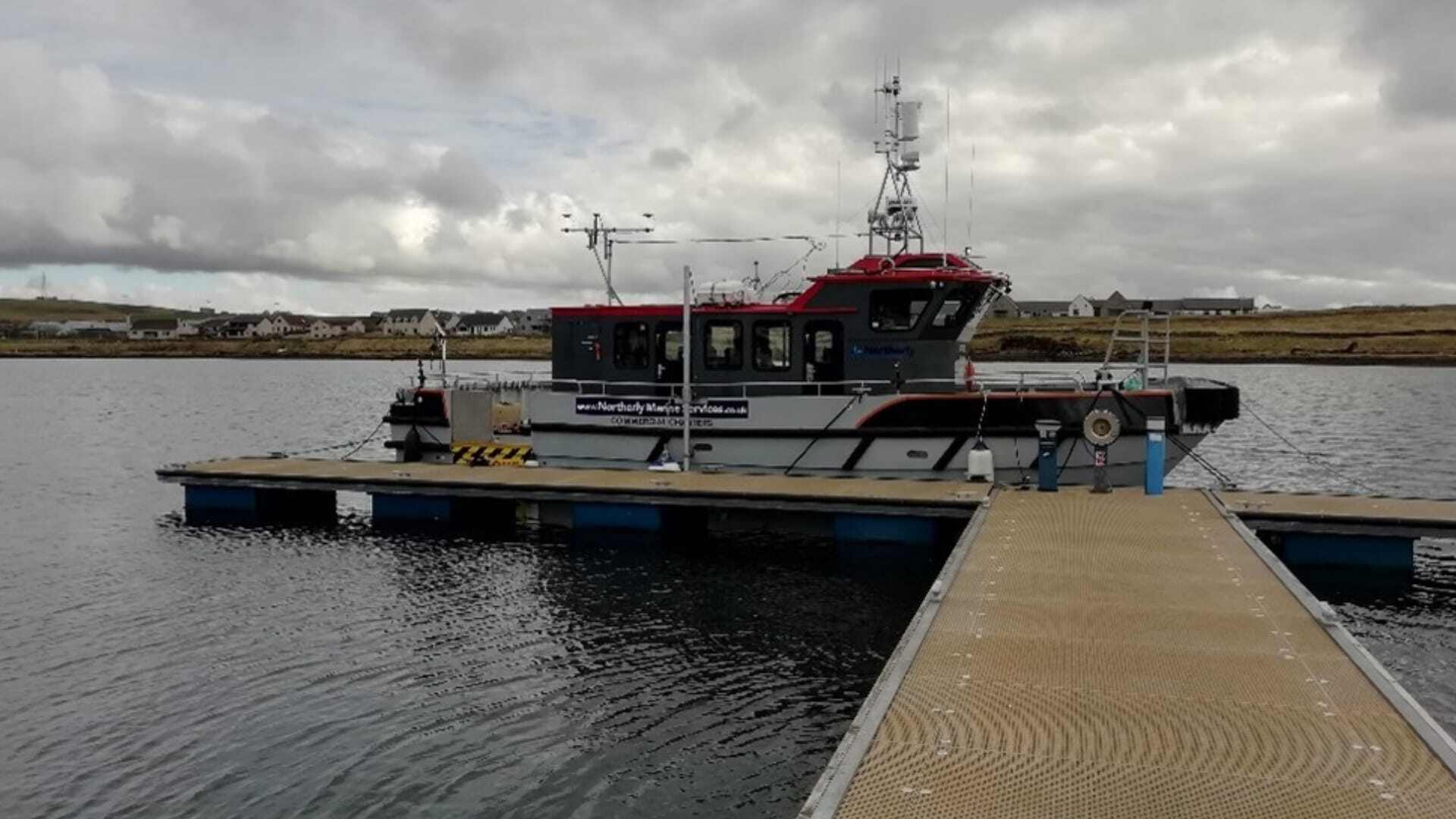
- Magnetometer - G-882 magnetometer in a 2 x G882 Magnetometers arrangement mounted to the TVG frame that was deployed from a davit on the back deck of the Northerly Explorer.
- Subsea realtime positioning of the towed sensors was achieved by using the Mini-Ranger 2 USBL while the IMU-108 provides high accuracy motion measurement.
- Survey Horizontal & Vertical Control was achieved by using the integrated POS MV vector based GNSS positioning system with integrated IMU for accurate measurement of vessel attitude during survey operations. and a secondary C-NAV 3050 DGNSS receiver set up to receive SF2 corrections.
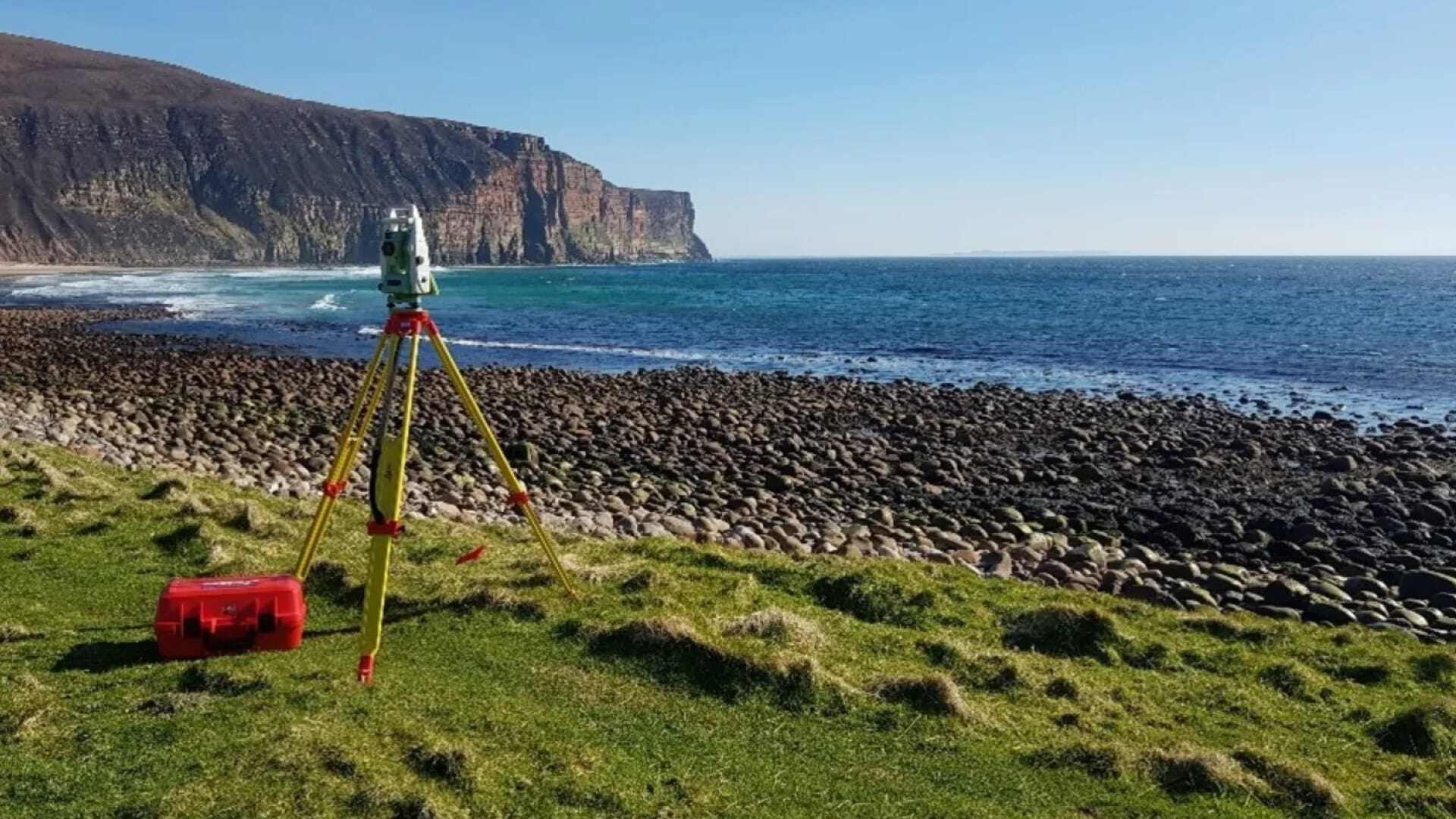
- Topographic Survey - deployed Leica GNSS kits comprising GX1230 GG GNSS receivers, RX1210T Keypads, AX1202 GG GNSS antenna, GFU28 GPRS modem and GAT18 GSM/GPRS antenna, Leica Robotic Total Stations TS16 R500 with CS16 controllers complete with the latest Viva software and Leica RTC360 high-definition laser scanner capable of gathering points up to 2,000,000 points per second.
Northerly Explorer was the ideal local vessel for the waters in the survey area with her twin hulls offering stability in larger seas and the shallow draft supporting her deployment for the shallow waters at both Hoy and the Mainland. Her twin propulsion offered reduced transit times and outstanding manoeuvrability thereby presenting her as the ideal platform for executing the12-hourly daily operations while providing a comfortable interior with adequate space for crew, surveyors, and client representatives.
Prior to commencement of data acquisition, OEG carried out performance checks and calibrations on the mobilized equipment ranging from MBES patch test, SSS, USBL and magnetometer altimeter checks. The Northerly Explorer underwent dimensional control survey to determine the relative coordinates (x,y,z) of the installed survey sensors and reference points aboard the survey vessel.
Also, a Survey Verification Test (SVT) was undertaken in advance of the UXO survey using a variety of UXO surrogates of known size, shape, and magnetic responses to validate equipment performance.
Thereafter, a 70m corridor was surveyed based on the center of the RPL. The 10m contour is located approximately 500m from land at Hoy and 650m from land at the mainland thereby translating to approximately 70 x 500m and 70 x 650m respectively. Both the geophysical data acquisition in the nearshore and topographic survey on land were executed concurrently with the geophysical data acquisition being executed in 2-stages to cater for the water depth variation.
- Stage 1 - MBES and SSS with dynamic lineplan to prevent data gap from too much data being gathered in deeper water and holidays being left in the shallower areas. This approach ensured a minimum 25% overlap on the previous swath with the SSS running the whole time and ensuring at least a 200% overlap of data.
- Stage 2 - Data acquisition with a combination of SBP and TVG Magnetometer. In this stage, OEG Renewables ran line spacing of 3m to allow for 100% magnetometer coverage, based on a Magnetometer separation of 1.5m on the TVG frame.
- Topographic Survey - OEG Renewables utilized GNSS RTK equipment in static mode to establish a network of primary control points across each site to allow for station descriptions a Leica GS16 NRTK GNSS for Survey Controls coordination and a roving GNSS with total station observations to link the control points together and acquire the data needed for the topographic survey elements of the project. The data was captured to RICS category F topographical survey standards suitable for plotting out at a scale of 1:200.
Full seafloor coverage was achieved across the survey area with adequate data overlap that exceeds project requirements at the nearshore landing areas. The technical specifications of the clients were exceeded for all the data sets.